| Budowa Hellcata posuwa się do przodu. Co prawda ta część relacji miała być poświęcona skrzydłom, ale muszę jeszcze nad nimi trochę popracować. Sporo ostatnio kleję i chyba następuje u mnie powoli pewne zmęczenie materiału. Postanowiłem odłożyć na razie na bok skrzydła i zabrać się za inne, prostsze (pozornie) rzeczy. | The build of the Hellcat is progressing. Although this part of the model build report was supposed to be about the wings, I still need to work on them a bit. I've been dealing a lot with the model lately, and I'm slowly getting tired of it. I decided to put the wings aside for a while and build some other, apparently simpler stuff. |
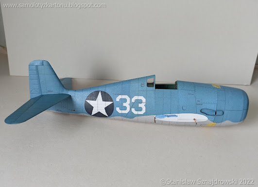
| Wykonałem usterzenie. Stałe części stateczników poziomych sklejało się bardzo dobrze, szkielet pasuje idealnie. Nieco problemów przysporzyło dopasowanie gotowych elementów do kadłuba - nie są przewidziane w tym miejscu oklejki / przejścia pomiędzy nimi, a kadłubem. Nie dopatrzyłem się takich elementów na zdjęciach prawdziwych F6F, więc ich brak jest jak najbardziej uzasadniony. Poszycie stateczników poziomych jest dobrze dopasowane do ogona, w paru miejscach jedynie delikatnie przeszlifowałem. Po doklejeniu było widocznych kilka niewielkich szparek, które wypełniłem klejem introligatorskim zmieszanym z farbką koloru kadłuba. | First, I made the rest of the tail. The horizontal stabilizers parts fit together very well, and the framework fits perfectly. Fitting the ready-made elements to the fuselage caused some problems - there are transitions between stabilizers and the fuselage here. I did not find such elements in the photos of the real F6F, so the lack of them is absolutely justified. The skin of the horizontal stabilizers fits very nice to the tail, I only slightly sanded it in a few places. After attaching to the fuselage, a few small gaps were visible. I filled them with bookbinding glue mixed with paint the color of the fuselage. It looks ok to me. |
| Białe pola w kształcie przekroju statecznika poziomego, które znajdują się po obu stronach ogona - miejsca przyklejenia stateczników są moim zdaniem za długie - po zamontowaniu elementów wystaje około 2 mm białego pola. Zamalowałem to, a po doklejeniu sterów wysokości i tak tego nie widać. | The white fields in the cross-section of the horizontal stabilizer, which are located on both sides of the tail - the adhesion points of stabilizers are too long in my opinion - about 2 mm of the white field protrudes after the elements are attached. I painted it blue, afterwards after sticking the elevators, you can't see it anyway. |
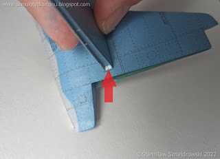
| Stery wysokości, a właściwie ich szkielety mają drobny błąd polegającym na zbyt płytkim umiejscowieniu elementów WD14 w częściach WD11. Korekta polegała na wycięciu głębszego wpustu w WD11. Błędne są też kolory zawiasów sterów wysokości (D4,D5), połowa z nich ma kolor kadłuba, połowa nie wiem czego. Właściwie nie ma to większego znaczenia, bo po ich zamontowaniu widać tylko ich krawędzie, które trzeba i tak wyretuszować. Przy sterze kierunku wszystko było w porządku. | The elevators, or rather their frameworks, have a little bug consisting in placing the WD14 elements too shallow in the WD11 parts. The correction consisted in making more place in WD11 for them. The colours of the elevator hinges (D4, D5) are also incorrect, half of them have the colour of the fuselage, and half of them do not know what. Actually, it doesn't really matter, because after mounting them you can only see their edges, which need to be retouched anyway. The rudder caused no problems, it fit nicely, both the framework and the skin. |
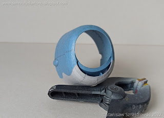
| W ostatniej odsłonie relacji pokazałem fragment osłony silnika. W międzyczasie udało mi się ją dokończyć. To była walka. Zewnętrzne oklejki pasują bardzo ładnie. Rzeczą, która sprawiła mi sporo problemów było wnętrze osłony. Wlot powietrza do chłodnicy oleju - ten charakterystyczny "uśmiech" jest dość trudny. Nie dziwię, się, że te części są wydrukowane podwójnie. Mimo użycia zamieszczonych kształtowników nie udało mi się poprawnie dopasować części A19, wydawała mi się za duża i zacząłem ją skracać, co niestety nie pomogło. Męczyłem się z tym ogromnie i ostatecznie wyciąłem z osłony uśmiechnięty wlot i zrobiłem go od nowa z zapasowego zestawu. A19 nie ma zapasu więc wykonałem ten i kilka innych elementów poszycia wnętrza we własnym zakresie. Niestety podczas tych manewrów oberwało się osłonie i widać na niej, że walczyłem. Najbardziej oberwał szew na dole, bo tam musiałem naciąć. Trudno. | In the last episode of the model build report, I showed a fragment of the engine cowling. In the meantime, I was able to finish it. It was hard. The outer skins fit very nicely. The thing that caused me a lot of problems was the inside of the cowling. Air intake to the oil cooler - this characteristic "smile" is quite tricky. No wonder these parts are double-printed. Despite the use of the given profiles, I did not manage to fit the A19 part correctly, it seemed too large and I started to shorten it, which unfortunately did not help. I struggled with it enormously and in the end, cut the smiling inlet out of the cowling and made it from the beginning from the spare kit. This included not the A19 part, so I made this and some other inner skins on my own. Unfortunately, the cowling has been damaged during these maneuvers and you can see that I was fighting. The seam at the bottom was hurt the most, because there I had to cut it. It happens. |
.jpg)
| Muszę jeszcze sprostować pewną rzecz. W poprzednim poście pisałem, że wypukłe osłony na osłonie silnika nie pokrywają się z wycięciami na kadłubie. Oglądając zdjęcia "z epoki" doszedłem do wniosku, że to mogło tak wyglądać. Niektóre plany pokazują, że te krawędzie były licowane, niektóre, że jest tam uskok. Nie potrafię stwierdzić na 100% jak to ma wyglądać. W każdym razie, elementy do wykonania "bąbli" (A41) są podwójne, jedne z czarnym konturem, drugie bez. Wybrałem oczywiście te bez i efekt mocno cieszy oko. | I have to correct one thing. In the previous post, I wrote that the convex covers on the engine cowling do not coincide with the cutouts on the fuselage. Looking at the photos from the "period", I came to the conclusion that it could have looked like this. Some blueprints show that these edges were faced, and some that there is a difference between "bubbles" and recess in the fuselage. I can't say 100% what it should look like. In any case, the items for making the "bubbles" (A41) are double, one with a black outline, the other without. Of course, I chose the ones without and the effect is very pleasing to the eye. |
| Na deser mam jeszcze ciekawostkę, innowację od GPM-u. Pośród elementów wyciętych laserem na tekturze grubości 1 mm są również elementy oznaczone jako F3. Są to zwijki, które po nawinięciu na drut służą jako podpory łopat śmigła. Konia z rzędem temu, kto to zwinie. Oczywiście jest to niedopatrzenie ze strony wydawcy, ale uśmiałem się do łez jak to odkryłem. | Now something funny. I found it as a curiosity, an innovation from GPM. Among the laser-cut frames on cardboard with a thickness of 1 mm there are also elements marked as F3. These elements should be wrapped very tight on a wire, and serve as supports for the propeller blades. I know no one who would be able to wrap them, this is simply impossible. Of course, this is an lapse of the publisher, very funny actually. |
| PS. Silnik już na miejscu, do następnego :-) | By the way, engine is already in his place :-) |

.jpg)
.jpg)
.jpg)
.jpg)
.jpg)
.jpg)
.jpg)
.jpg)
.jpg)
.jpg)
.jpg)
.jpg)
.jpg)
.jpg)
.jpg)
.jpg)
.jpg)
.jpg)
.jpg)
.jpg)
.jpg)
.jpg)
.jpg)
.jpg)
.jpg)
.jpg)
.jpg)
.jpg)
.jpg)
.jpg)
Brak komentarzy:
Prześlij komentarz