
| Dzisiaj zaczniemy od cytatu z opisu budowy: "Moja mała uwaga na temat silnika, otóż po jego zmontowaniu z popychaczami i rurami wydechowymi zrobiło się tam tak ciasno, że prawie nie było widać silnika, najlepiej wyglądał bez tych wszystkich rur (oprócz wydechowej oczywiście) ale to tylko moja sugestia". Jeżeli autor ostrzega przed klejeniem makiety silnika, którą sam zaprojektował to znaczy, że trzeba mieć się na baczności. | Today we will start with a quote from the manual: "My little note about the engine, after it was assembled with all the push rods and exhaust pipes it got so cramped that you could hardly see the engine, it looked better without all these pipes (except the exhaust pipe of course) but that's just my suggestion." If the author warns against building the engine imitation, which he designed himself, it means to me that I have to be careful by assembling it. |

| Zacząłem od rzeczy, która została mi do dokończenia z początkowego etapu budowy, a mianowicie części p9 i p10, stanowiących poszycie przedniej części kadłuba. Nie do końca rozumiem to rozwiązanie, bo skorupka sklejona z tych dwóch elementów musi być nasunięta na istniejący już element poszycia p11. W elemencie p10 postanowiłem uplastycznić nadrukowane na nim wklęsłe "łezki". Dorobiłem je we własnym zakresie. Żeby je wkleić musiałem także rozpruć nieco element poszycia znajdujący się pod spodem (p11). Na tym etapie częściowo skleiłem także osłonę silnika po to, żebym mógł później na bieżąco dopasowywać do niej silnik. Projekt oczywiście nie zakładał czegoś takiego jak paski łączące. Musiałem je sobie dorobić. Pozostały jeszcze wypukłości, pod którymi kryją się osłony mechanizmu popychaczy zaworów, ale te zostawiam sobie na sam koniec. | I started with the finishing that I didn't complete at the initial stage of the build, namely parts p9 and p10, which are the plating of the front part of the fuselage. This solution is not clear to me, because the shell glued together from these two elements must be slid over the existing p11 plating element. In the "p10" element, I decided to cut out the "tears" printed on it. I made them on my own. In order to paste them, I also had to cut out a little bit of plating underneath (p11). At this stage, I also partially glued the engine nacelle so that I could adjust the engine to it later. Of course, the design did not involve anything like connecting strips. I had to do them myself. There are also "bubbles" on the cover. Underneath there will be later the rocker arms from valve mechanism, but I leave these for the end. |


| RWD-17W był napędzany 7 cylindrowym, chłodzonym powietrzem silnikiem gwiazdowym Bramo SH-14 (SH od Siemens-Halske). Ta niemieckiej produkcji jednostka napędowa znalazła zastosowanie w wielu ciekawych konstrukcjach z lat 20-stych i 30-stych XX wieku. Listę maszyn napędzanych przez Bramo SH-14 można zobaczyć tutaj. Przy budowie silnika posiłkowałem się genialnym modelem 3D, który można zobaczyć na forum military-meshes.com. Na podstawie tych grafik wzbogaciłem nieco silnik zamieszczony w modelu. Dokładniejsza analiza rysunków montażowych pokazuje, że podobnie jak przy pływakach mamy tu dwie alternatywne, istniejące równolegle rzeczywistości. | The RWD-17W was powered by a 7 cylinder air-cooled Bramo SH-14 radial engine (SH from Siemens-Halske). This German-made power unit was used in many interesting constructions from the 1920s and 1930s. A list of the machines powered by Bramo SH-14 can be seen here. When building the engine, I used a brilliant 3D model that can be seen on the military-meshes.com forum. Based on these graphics, I have enriched the engine in the model a bit. A more detailed analysis of the assembly drawings shows that we have two alternative realities existing on the drawings (similarly to the floats). |

| Osłony popychaczy zaworów występują w dwóch wersjach (zaznaczone na czerwono)- te na rysunku po lewej u góry przypominają rzeczywisty ich wygląd, ale notatka obok informuje, że ze względu na skalę elementy zostały uproszczone. Poniżej znajduje się rysunek z kanciastymi osłonami. Nie miałem pojęcia, jak z elementów 4c wykonać te osłony. Ostatecznie, naciąłem je na liniach zagięcia (zaznaczyłem na czerwono) i wkleiłem pomiędzy tekturę 0,8 mm. Chyba nawet o to chodziło autorowi. Wyciąłem, oszlifowałem i nakleiłem na cylindry. Kolejną ciekawostką jest to, że układ wydechowy (zaznaczone na niebiesko), a konkretnie 7 rur odprowadzających spaliny do zbiorczego pierścienia wyglądają na rysunku montażowym tak, jakby miały być wykonane ze zwiniętych w rurki kawałków kartonu. Są oznaczone jako elementy 5c. Na próżno ich szukać w wycinance - nie istnieją, jest tylko kiepski szablon według którego można je wykonać. | The covers of the rocker arms come in two versions (marked in red) - the ones in the upper left figure resemble their actual appearance, but the note beside informs that the elements have been simplified due to the scale. Below there is a drawing with angular covers. I had no idea how to make these covers from parts 4c. Finally, I cut them on the fold lines (marked in red), bend and pasted between 0.8 mm cardboard. I guess that was even what the author meant. I cut them, sanded and glued to the cylinders. Another interesting fact is that the exhaust system (marked in blue), namely the 7 exhaust pipes leading to the collective ring, look in the assembly drawing as if they were to be made of pieces of cardboard rolled up into tubes. They are marked as parts 5c. It is a waste of time to look for them in the model cutout - they do not exist, there is only a poor template according to which they can be made. |

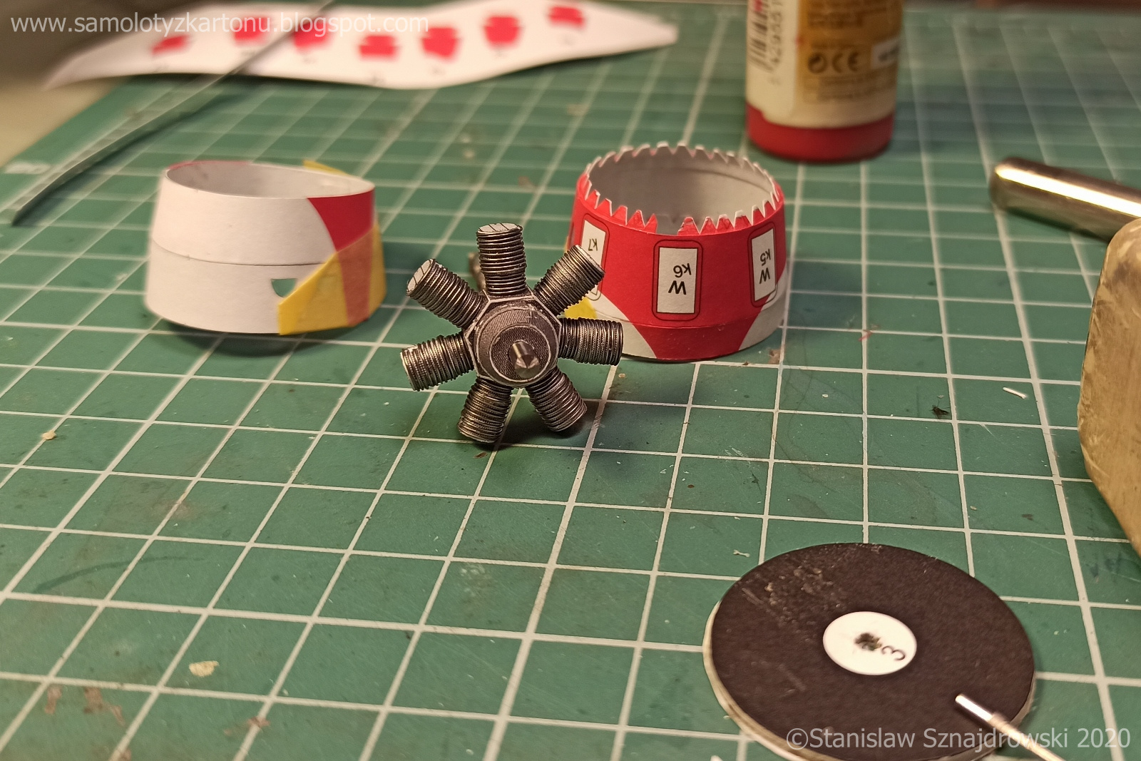
| Sklejenie centralnej części silnika wraz z cylindrami nie sprawiło najmniejszych kłopotów. Cylindry owinąłem drutem cynowym 0,2 mm, tak aby uzyskać imitację żebrowania. Całość będzie docelowo i tak malowana. Następnie zabrałem się za najbardziej intrygującą część, mianowicie układ wydechowy. Jest on dość osobliwy ze względu na umieszczenie go od frontu, a nie od tyłu. Najpierw, z elementów dostępnych w wycinance, wykonałem pierścień zbiorczy. Uplastyczniłem nieco jego przednią część masą modelarską, którą po wyschnięciu oszlifowałem. Kolejnym krokiem było wykonanie 7 rur odprowadzających spaliny z cylindrów do wspomnianego kolektora. Te musiałem już zrobić od podstaw. Jako materiału użyłem cienkiego papieru, z którego zwinąłem sobie trochę rurek długości około 2 cm i średnicy około 1,5 mm. Usztywniłem je klejem CA, a następnie poprzycinałem i posklejałem je tak, aby uzyskać odpowiednie kształty rur. Tak samo zrobiłem ze zbiorczą rurą wydechową, która odprowadza spaliny z pierścienia na zewnątrz. Swoją drogą, uważam, że ta pojedyncza, długa, wygięta w literę "S", zwisająca pod kadłubem rura jest urocza. | Glueing the central part of the engine with the cylinders did not cause any problems. I wrapped the cylinders with 0.2 mm tin wire in order to imitate the ribs. The whole thing will be painted anyway. Then I started the most intriguing part, namely the exhaust system. It is quite peculiar because it is placed at the front, not the rear. First, I made a collecting ring from the elements available in the cutout. I improved its front part a bit with a modelling putty and sanded it after drying. The next step was to make 7 exhaust pipes from the cylinders to the aforementioned collector. I had to do these pipes from scratch. As a material, I used thin paper, from which I rolled some tubes about 2 cm long and about 1.5 mm in diameter. I stiffened them with CA glue, then cut them and glued them together in order to obtain the appropriate shapes of the pipes. I did the same with the exhaust manifold, which discharges the exhaust gases from the ring to the outside. By the way, I found this single, long, S-bent pipe hanging under the fuselage to be cute. |


| Kiedy już przygotowałem wszystkie potrzebne do złożenia silnika elementy zabrałem się za malowanie. W ruch poszły farby Vallejo widoczne na zdjęciu oraz aerograf. Projekt modelu nie przewiduje wewnętrznego poszycia osłony silnika więc psiknąłem ją od wewnątrz kolorem aluminium. Mieszając ze sobą metaliczne kolory z rdzawym brązem i czerwienią oraz nakładając kilka cienkich warstw uzyskałem zadowalający efekt na układzie wydechowym. | After I prepared all the elements needed to assemble the engine, I started painting. I used Vallejo paints visible in the photo and airbrush. The design of the model does not include the internal plating of the engine cover so I painted it with aluminium colour from the inside. By mixing metallic colours with rusty brown and red, and by applying a few thin layers, I obtained a satisfactory effect on the exhaust system. |


| Po pomalowaniu części składowych silnika złożyłem je w całość. Gotowa makieta silnika Bramo HS 14 wygląda tak: | After painting the engine components, I put them together. The finished model of the Bramo HS 14 engine looks like this: |


| Po ukończeniu silnika nadszedł moment umieszczenia go w częściowo wykonanej osłonie. Na tym etapie brakowało na niej jeszcze wyobleń nad osłonami popychaczy zaworów. Był to celowy zabieg dzięki któremu, podczas montażu silnika w osłonie mogłem przez wycięte w niej osłonie korygować jego położenie. Autorowi modelu należą się słowa uznania za zaprojektowanie owych "bąbli" na osłonie silnika. Po pierwsze za to, że nie mają czarnego konturu, dzięki czemu miejsca łączeń nie rzucają się w oczy. Po drugie - są po prostu dobrze narysowane i ładnie się sklejają. Jeden malutki kamyczek w ogródku to błędne oznaczenie dwóch elementów (na odwrót). Po naklejeniu wyobleń przykleiłem "kapsułę mocy" do kadłuba. Montaż rury wydechowej pod spodem zostawiam sobie na sam koniec. Uzyskany efekt bardzo mi się podoba. | After completing the engine, it's time to put it in a partially made nacelle. At this stage, the "bubbles" above the valves covers were still missing. It was a deliberate operation, thanks to which, when mounting the engine in the nacelle, I could adjust its position through the cut holes. The author of the model deserves praise for designing these "bubbles" on the engine nacelle. First of all, for the fact that they do not have a black outline, thanks to which the joining edges are not visible. Second - they are just well-drawn and they stick together nicely. There is only one little mistake - the wrong designation of two elements (vice versa). After sticking the "bubbles", I glued the engine compartment to the fuselage. I leave the assembly of the exhaust pipe underneath for the end. I like the effect very much. |


| Wrócę jeszcze na chwilę do cytatu zamieszczonego na początku. Osobiście lubię detalizowane silniki i inne drobiazgi. Chętnie poświęcam czas "modelarskiej biżuterii" i taka "zegarmistrzowska robota" sprawia mi sporo satysfakcji. Nawet jeśli później jest nie widoczna, pozostają zdjęcia, na których dokumentuje postępy oraz świadomość tego, że coś takiego się zbudowało. Nie wszyscy modelarze reprezentują ten sam pogląd co ja i oczywiście każdy ma prawo kleić tak jak mu się podoba. Jeżeli jednak autor zniechęca do klejenia makiety silnika, bo nie będzie jej widać (co też nie jest do końca prawdą, bo widać ją moim zdaniem nieźle) to pojawia się pytanie po co w ogóle ją projektował? Całość bawi mnie tak bardzo dlatego, że skleiłem ten silnik i uważam, że to jeden z lepiej zaprojektowanych fragmentów tego modelu, za który autorowi należą się brawa. Może lepiej było napisać, że mniej zaawansowanym modelarzom odradza klejenie kompletnej makiety silnika? | I will come back for a moment to the quote at the beginning. Personally, I like detailed engines and other little things. I like to devote my time to "jewellery" and such "watchmaking work" gives me a lot of satisfaction. Even if it is invisible later, there are still photos that document the progress and the awareness that something like this has been built. Not all modellers have the same view as me, and of course, everyone has the right to build as they like. However, if the author discourages from glueing the engine imitation because it will not be visible (which is also not entirely true, because you can see it well, in my opinion), the question arises why did he design it at all? The whole thing amuses me so much because I glued this engine together and I believe that it is one of the better-designed fragments of this model, for which the author deserves applause. Maybe it was better to write that less advanced modellers are advised against glueing a complete engine imitation? |
należą się TOBIE duże brawa!
OdpowiedzUsuńPięknie,jak zawsze profesjonalne. Pozdrawiam
OdpowiedzUsuńSilniczek jak żywy. Pozdrawiam i dzieki za przydatne patenty. Pozdrawiam Tomek
OdpowiedzUsuń