
| Po tym jak udało mi się skleić fragment przodu wraz z kabiną przyszedł czas na centralną część kadłuba. Wiadomym było dla mnie od początku, że ta część budowy będzie trudna i decydująca - na tym etapie popełniłem błędy przy klejeniu MiGa-23 MF. Pozornie niewielkie niedociągnięcia doprowadziły później do tego, że model poleciał lotem koszącym do śmietnika. Mądrzejszy o doświadczenie zabrałem sie do pracy. | After I managed to build the front part with the cockpit, it was time for the central part of the fuselage. It was known to me from the beginning that this part of the construction would be difficult and decisive - at this stage, I made mistakes when building the MiG-23 MF four years ago. Seemingly minor shortcomings later led the model to fly to the garbage can. Smarter about the experience, I started the work. |

Zacząłem oczywiście od wycięcia wręg, wydawnictwo
Answer oferuje również elementy wycięte laserowo, ale nie skorzystałem z tej
opcji. Lubię wycinać :) Szkielet centralnej części kadłuba jest dość
skomplikowany. Mieści się w nim także mechanizm poruszania skrzydłami, co
dodatkowo komplikuje sprawę. Sercem tego mechanizmu jest zębatka grubości około
4 mm (cztery warstwy tektury 1 mm) umieszczona w osi kadłuba. | I started with cutting the frames, the Answer publishing house also offers a laser-cut framework, but I did not use this option. I like cutting :) The framework of the central part of the fuselage is quite complicated. There is also a swap-wing movement mechanism, which further complicates the matters. The heart of this mechanism is a 4 mm thick rack (four layers of 1 mm cardboard) located along the fuselage axis. Then I assembled the framework together from the available parts and started trying the skin on it. |


| Wszystkie trzy elementy poszycia (43,44,45) zostały wzmocnione podposzyciem z cienkiego papieru wklejonego na butapren, część 45 dostała dodatkową warstwę na grzbiecie. Przed wklejeniem wzmocnień uformowałem elementy tak, aby pasowały idealnie do szkieletu. Dwa przednie paski poszycia skleiłem ze sobą tworząc skorupę, którą wkleiłem na szkielet. Następnie zabrałem się za wzbogacenie szkieletu o wzmocnienia w górnej części. W poprzednim MiG-u zapadło mi się poszycie na grzbiecie. Chciałbym tego uniknąć więc wkleiłem trochę dodatkowych żeberek. Z tego samego powodu podklejka części 45 jest podwójna. Szczególnie wrażliwym na zapadnięcie jest miejsce, w którym przykleja się "garb" przebiegający wzdłuż osi symetrii. | All three elements of the skin (43,44,45) were reinforced with a thin paper underlay glued onto butaprene, part 45 was given an additional layer on the back. Before glueing the reinforcements, I shaped the elements to fit the framework perfectly. I glued the two front strips of the sheathing together to form a shell which I glued onto the framework. Then I started to enrich the construction with reinforcements in the upper part. In the previous MiG, the skin on the upper part of fuselage collapsed. I'd like to avoid that so I glued in some extra ribs. For the same reason, the underskin of part 45 is double. Particularly susceptible to collapse is the place where later will be glued the "hump" along the axis of symmetry. |


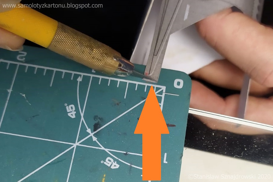
| Kluczowym dla powodzenia budowy momentem było połączenie skorupy cz. 45 ze szkieletem. Trzeba ją na bieżąco dopasowywać do cz. 51 (poszycie grzbietu), 37 (ostatni segment przedniej części kadłuba) oraz cz. 43. Chodzi o to, żeby część 51 tworzyła z przylegającą cz. 37 i 45 równą powierzchnię i żeby nie było pomiędzy nimi szpar. Poszycie cz. 45 musiałem po obu stronach skrócić w miejscu styku z cz. 43 o około 0,6-0,8 mm, po tej korekcie wszystko spasowało się idealnie. Miejsce cięcia pokazuje ostatnie zdjęcie. | The crucial moment for the success of the build was the connection of part 45 (formed as a shell) with a framework. It has to be adjusted to part 51 (ridge plating), 37 (last segment of the front part of the fuselage) and part 43. The point is that part 51 should form with the adjacent part. 37 and 45 an even surface and that there are no gaps between them. I had to shorten part 45 on both sides at the point of contact with part 43 by about 0.6-0.8 mm, after this correction everything fits perfectly. The place of the cut is shown in the last photo. |


Jedną z tych rzeczy, która powoduje, że MiG-23 tak mnie fascynuje jest zespół głównego podwozia. To jest prawdziwe inżynieryjne dzieło sztuki. Zawsze gdy na nie patrzę nie mogę wyjść z podziwu, że potrafiło utrzymać samolot o masie startowej 18 ton oraz, że w pozycji złożonej jest zapakowane w komorę jak szafa z Ikei w kartonie. Piszę o tym dlatego, że na tym etapie budowy trzeba skleić komory podwozia, które są częścią tego cuda. Przez to, że znajdują się na bocznych ścianach kadłuba są bardzo dobrze wyeksponowane. Miałem nie dodawać do modelu nic od siebie, ale nie potrafię się oprzeć przed wklejeniem imitacji okablowania, instalacji elektrycznej, hydraulicznej i różnych innych urządzeń, których nie potrafię wymienić po imieniu. Naturalnie konsekwencją tego kroku będzie to, że przednią komorę też będę musiał waloryzować. Najpierw komory w standardzie: | One of the things that makes the MiG-23 so fascinating to me is the main landing gear. This is a real engineering masterpiece. Whenever I look at them, I cannot stop wondering that it was able to hold an aircraft with a take-off weight of 18 tons and that in the folded position it is packed in a wheel bay like an Ikea wardrobe in a carton. I am writing about it because at this stage of construction it is necessary to put into the fuselage the wheel bays, which are part of this masterpiece. Due to the fact that they are located on the side walls of the fuselage, they are very well exposed. I wasn't supposed to add anything from myself to the model, but I couldn't resist making imitation of electrical and hydraulic installation and some other stuff. Naturally, the consequence of this step will be that I will also have to add something extra to the front wheel bay. First, the wheel bays as standard: |


| Zanim zabrałem się do pracy przejrzałem sporą ilość
zdjęć komór podwozia MiG-a-23 dostępnych w Internecie, a także we własnych
zbiorach. Niestety im więcej zdjęć oglądam tym bardziej jestem zagubiony w tej
masie przewodów i urządzeń w nich upchanych. Niestety zdjęcia muzealnych
egzemplarzy nie są zbyt pomocne - samoloty te są często zdekompletowane.
Waloryzację komór przeprowadziłem głównie na podstawie renderów zamieszczonychna stronie sklepu Eduarda oraz zdjęć żywicznych komór Trumpetera. Zdjęcia
prawdziwych maszyn posłużyły jedynie jako dodatkowe źródło. Bardzo przydatny był też film znaleziony na Youtube: https://www.youtube.com/watch?v=mHr5-dlDX8o. Na początku
wykonałem trochę kartonowych części, które zaobserwowałem na zgromadzonych
materiałach. Następnie zabrałem się za elementy z drutu, tu zastosowałem różne
średnice i rodzaje drutów - od miedzianego 1,2 mm do cynowego 0,2. W pierwszej
kolejności poszły najgrubsze i średnie rury (żółte i czarne), potem cieńsze, a
na końcu okablowanie. Kolorystyka jest w dużej mierze przypadkowa, tak jak
wspomniałem, przeglądając zdjęcia oryginałów nie byłem w stanie określić jak to
powinno wyglądać, wszędzie jest inaczej, a niektóre motywy się powtarzają. Pokrywy
cz. 42a zrobiłem jako wklęsłe (pod nimi wyciąłem dziurki) oraz dodałem śruby z
kropelek kleju introligatorskiego, które później pomalowałem. Dodatkowo
zrobiłem niebieską kredką imitację napisów eksploatacynych na tych pokrywach. Zdjęcia poniżej odpowiadają kolejności budowy. | Before I got down to work, I looked through a large number of photos of the MiG-23 wheel bays available on the Internet, as well as in my own collection. Unfortunately, the more photos I watch, the more I am lost in this mass of wires and devices crammed into them. Unfortunately, the photos of the museum objects are not very helpful - these planes are often incomplete. The valorization of the wheel bays was carried out mainly on the basis of graphics posted on the Eduard store website and photos of Trumpeter's resin wheel bays. Pictures of real machines served only as an additional source. The video found on Youtube was also very useful: https://www.youtube.com/watch?v=mHr5-dlDX8o. In the beginning, I made some cardboard parts which I observed on the collected materials. Then I started with the wire elements, here I used various diameters and types of wires - from copper 1.2 mm to tin 0.2. I assembled first the thickest and medium pipes (yellow and black), then the thinner ones, and finally the wiring. The colors are largely random, as I mentioned, looking at the photos of the originals, I was not able to determine what it should look like. It looks a little bit different everywhere, but some things are repeatable and looks always the same (e.g. yellow pipes). I made covers part 42a concave (I cut holes under them) and added screws from bookbinding glue droplets, which I later painted. In addition, I made an imitation of the operating inscriptions on these covers with a blue crayon. The photos below correspond to the order of construction. |


| Jestem zadowolony z moich komór, choć nie każdy
kabel przebiega jak w rzeczywistości. Starałem się zainstalować je tak, aby
każdy gdzieś prowadził i żeby przypominało to instalacje w komorach prawdziwego
MiG-a. Ten etap budowy uważam za zamknięty, do komór wrócę przy montażu
podwozia. | I am happy with my wheel bays, although not every wire is as it really was. I tried to install them so that everyone leads somewhere and that it resembles the installations in the wheel bays of a real MiG. I consider this stage of construction closed, I will return here when assembling the landing gear. |
Jest co podziwiać. Według mnie dzieła sztuki. Jakby nie powiedzieć pięknie. Ogromna precyzja. Pozdrawiam serdecznie.
OdpowiedzUsuń